CCSi TechNotes: Patent Number 5,526,693 Oscillating Rotor
FIG. 1, but with the curemeter closed.
Curemeter
United States Patent 5,526,693
Wise June 18, 1996
Oscillating Rotor Curemeter
Abstract
There is disclosed a device for testing the cure properties of a
i
Wise; Raleigh W. (Ft. Myers, FL)
Assignee: Wise—Sullivan, Inc. (Akron, OH)
Appl. No.: 306174
Filed: September 14, 1994
U.S. Class: 73/843; 73/54.39
Intern’l Class: G01N 003/24; G01N 011/16;
G01N 011/14; G01N 033/44
Field of Search: 73/866,843,54.39
| 3387490 | Jun., 1968 | Wise | 73/54. |
|---|---|---|---|
| 3479858 | Nov., 1969 | Umeno et al. | 73/843. |
| 3488992 | Jan., 1970 | Veith et al. | 374/48. |
| 3531996 | Oct., 1970 | Harris et al. | 73/865. |
| 4337646 | Jul., 1982 | Fraleigh | 73/54. |
| 4343190 | Oct., 1982 | Danko et al. | 73/54. |
| 4421424 | Dec., 1983 | Price et al. | 374/48. |
| 4539838 | Sep., 1985 | Fraleigh | 73/54. |
| 4552025 | Nov., 1985 | Barker et al. | 73/846. |
| 4829830 | May., 1989 | Tosaki | 73/847. |
| 4953406 | Sep., 1990 | Putman | 73/843. |
Primary Examiner: Noland,Thomas P.
Attorney, Agent or Firm: Nielsen,Olaf
Claims
- In a device for determining the state of cure of a thin section elastomer sample, such device having first and second dies, means to move one die selectively into and out of contact with the other die, a rotor oscillatable through a shaft thereof, and means to measure and record torque in the shaft as an indication of cure, the improvement comprising a deep recess in the first die, the rotor supported in said recess by its shaft which extends from an underside of a head of the rotor and through the first die, and elastomeric means in said recess having an upper surface contiguous with, and matching the contour of, the underside of the rotor head to prevent intrusion of sample materials under the head, said upper surface extending laterally beyond the head of the rotor to form a sample support.
- The device of claim 1, wherein said upper surface has a diameter substantially greater than a diameter of the head of the rotor.
- The device of claim 1, wherein said elastomeric means comprises a cured silicone member.
- The device of claim 1, wherein said recess is
cylindrical, and said elastomeric means substantially annular. - The device of claim 1, wherein said elastomeric means has a height substantially less than the depth of said recess.
- The device of claim 1, wherein said elastomeric means forms with the second die a cavity for a sample having a thickness substantially less than a height of said elastomeric means.
Description
Background of the Invention
One classification that may be made of
Veith et al U.S. Pat. No. 3,488,992 (1970)
Barker et al U.S. Pat. No. 4,552,025 (1985)
Burnin et al U.S. Pat. No. 5,079,956 (1992)
Putman U.S. Pat. No. 4,953,406 (1990)
Danko et al U.S. Pat. No. 4,343,190 (1965)
Tosaki U.S. Pat. No. 4,584,812 (1986)
Harris et al U.S. Pat. No. 3,531,996 (1970)
Decker U.S. Pat. No. 3,681,980 (1972)
Price et al U.S. Pat. No. 4,421,424 (1983)
Turner et al U.S. Pat. No. 4,275,600 (1981)
Wise U.S. Pat. No. 3,387,490 (1968)
Beatty et al U.S. Pat. No. 3,182,494 (1965)
Kitchen U.S. Pat. No. 4,559,812 (1985)
Several common threads run through the disclosures of the above—mentioned test devices: the test sample materials are located on top of as well as under the rotor head, i.e. the rotor head is embedded within the rubber samples during testing
When a test device of the above type is opened, a substantial labor and
The above procedures unnecessarily prolong the time the device must remain open before it is recharged with a new sample, and the result is a loss of heat which must be recovered when the device again closes. Furthermore, without the heat sink means of the present invention to provide some temperature control, unacceptable heat losses are also experienced from the rotor through its associated drive and support means.
The results of these shortcomings are that the successive testing of samples shows poor
Summary of the Invention
This invention overcomes the above disadvantages by providing a
There is disclosed a means and method for testing an elastomeric material by providing for locating a test sample only on top of the rotor head, like a cap thereon, rather than surrounding it top and bottom. This results in thinner—section samples more easily removable from the test device than the prior art samples which embed the rotor head completely.
The object of the invention is therefore to provide a test device from which test samples of
Brief Description of the Drawings
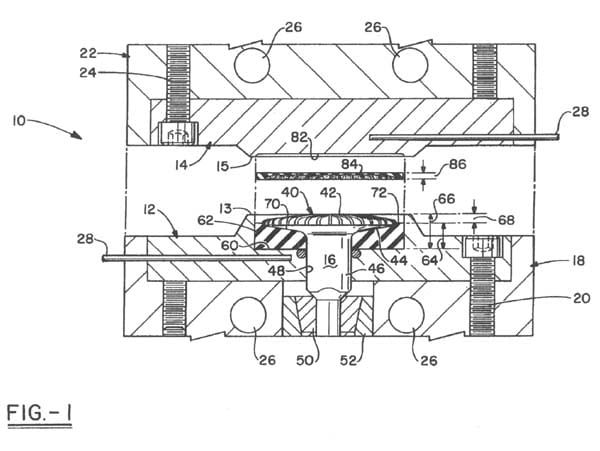
FIG 1 is an elevational view, in
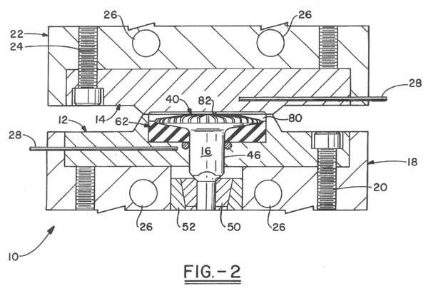
Fig. 2 is an elevational view, in
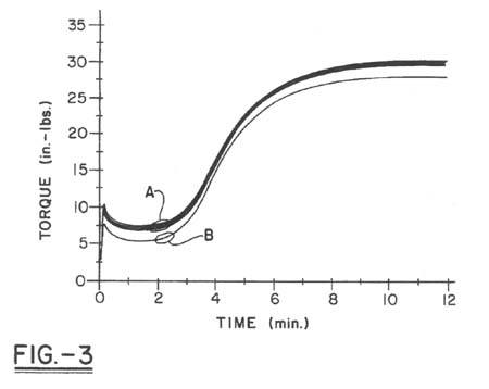
FIG. 3 is a graphical representation of
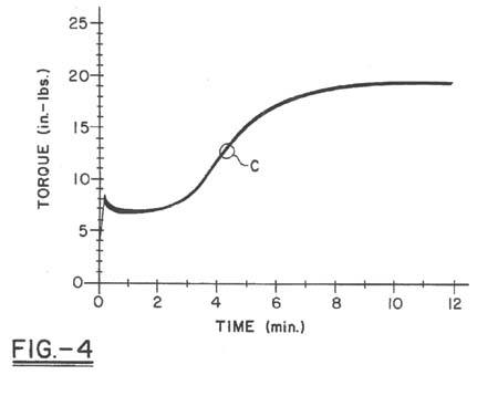
FIG. 4 is a graphical representation of
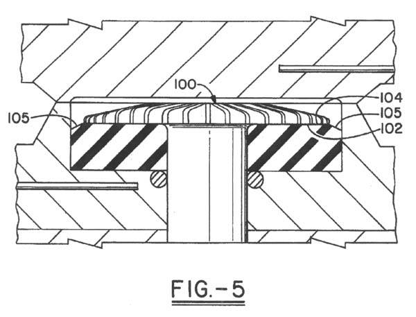
FIG. 5 is a partial,
(When selected, Figures will appear in a separate window. This allows you to continue to read the document while the Figure is loading, lessening the time of interruption.)
Detailed Description of a Preferred Embodiment
In FIG. 1 and FIG. 2 are shown an assembly suited for use in a
Referring specifically to FIG. 1 and FIG. 2, there is shown at 10 an assembly having a circular lower metal die 12 and a circular upper metal
The dies 12 and 14 are heated by heaters 26, well—known in the art and not further detailed here, and their temperatures controlled by well—known sensors 28.
The rotor 16, of heat—conductive metal, comprises a head 40 having a substantially domed or
Lower die 12 is provided with a deep cylindrical recess 60, which is fitted with an annular heat—sink and sealing member 62, preferably made of cured, low modulus silicone rubber; it has a main axial height 64 which is less than the depth 66 of the recess, leaving a small cylindrical portion 68 at the top of the recess, as explained hereafter. The top surface 70 of the member 62is substantially contiguous
The peak of the rotor top surface 42 is leveled with the lower die—land 13. The top surface 70extends laterally beyond the head 40 of the rotor, forming a small annular sample—support surface portion 72 of the member 62 which separates the rotor head from the cylindrical wall portion 68, and also prevents metal—to—metal contact between the recess wall and the rotor head.
When the dies 12 and 14 are moved into closed position, a test cavity 80 (see FIG. 2) is created substantially between the portion 68 of the lower die 12, the seal portion 72, the rotor top surface 42, and the recess 82 in the upper die 14. The sample formed therein is seen at 84 in FIG. 1, and has an edge thickness 86 substantially less than the main height 64 of the seal member 62.
In a useful relationship, the seal height 64 is approximately three times the edge thickness 86. This ensures that, as the oscillation proceeds, the rotor head will tend to flex the heat—sink/seal material, rather than slipping over its surface. Although the seal contributes some torque to the sample measurement, a correction for this can be
The volume of sample material charged into the device is usually slightly greater than the capacity of the cavity 80, and the closing together of the dies under pressure will therefore normally result in a small amount of the sample being squeezed out or extruded between the die—lands 13 and 15.
The top surface of portion 72 of the heat sink/sealing member 62 is lower than the level of the die—land 13 by the amount of portion 68 to ensure that seal material will not be squeezed out between the die—lands together with any excess sample material.
In FIG. 3 is shown graphically a number of tests conducted according to ASTM Standard Test Method D2084—91, wherein the biconical head of a disk rotor is completely embedded in a rubber sample. The curves generated are the typical S—curves obtained with ASTM D2084—91; since the sample totally surrounds the biconical rotor—head, its volume and gauge are shown to cause the torque to range upwards toward 35 inch—pounds. Time is plotted toward 12 minutes.
It will be noted that one family of curves is designated “A”. It represents a number of test—cycles, the last one of which necessitated removal of the rotor from the curemeter in order to remove all of the cured sample. The rotor and the area of the lower die where the rotor shaft is inserted was cleaned off, and the rotor re—inserted in the curemeter, but now it was not possible to fix its axial location exactly as before.
Consequently, the next sample, shown by curve “B” and representing a family of test results which will obtain until the rotor must next be removed for servicing, is seen to show an entirely new range of values. Reproduceability of test results is thus poor. Even the curves of family “A” show, for example minimum torque values ranging over almost one—half inch—pound.
In FIG. 4, the same rubber compound as in FIG. 3 is subjected to testing in the device of the invention, the sample here being thinner than in the previous tests, since it is loaded into the curemeter only on the top of the rotor, and is sealed from intrusion under the head of the rotor by the contiguous seal/heat—sink. Thus, the torque values extend only toward 25 inch—pounds. It will be noted that the family of curves “C” tracks closely, and there are no rogue aberrations as in FIG. 3. Good reproduceability of test results has now been obtained. Minimum torque values vary less than approximately one—third inch—pound.
FIG. 5 shows a modification wherein the rotor head 100 has a planar underside 102 contiguous with, and matching the contour of, the top planar surface 104 of the seal 106. The laterally extending annular band portion 105 is shown canted slightly toward the bottom of the recess.
Although the dies 12 and 14 are shown as circular, the recess 60 and its wall section 68 as cylindrical, and the heat sink/seal 62 and band 72 as annular, it will be understood that other shapes may be used successfully, and that other modifications may occur to those skilled in the art without departing from the scope of the invention.
Contact CCSi to request calibration services.