CCSi TechNotes: Basics of Rockwell MicroHardness Testing
Application
The microhardness testing of materials allows for the determination of the hardness of small or thin specimens and small areas of larger specimens. Microhardness testing is commonly used to determine characteristics of thin sheets, foils, fine wire, epoxies, paints, etc. and is often employed in R&D applications where a material’s microstructure is of interest.
Microhardness is especially useful in determining hardness variations caused by hardening, quenching, plating, fabrication, welding or annealing, bonding, etc. Microhardness testing can be accurately employed using loads as slight as 1 gram, somewhat less and considerably more in certain situations.
Photographic equipment, which enhances the image of the indentation, is widely used to determine the characteristics of specimen’s microstructure in and around the area of the indentation.
Vickers Scale
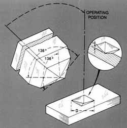
ASTM E92 (Vol. 03.01) Standard Test Method for Vickers Hardness of Metallic Materials describes the Vickers microhardness test as “… a number related to the applied load and the surface area of the permanent impression made by a square—based pyramidal diamond indenter having included face angles of 136º … all four faces of the indenter shall be equally inclined to the axis of the indenter (within ± 30 min) and meet at a sharp point, that is, the line of the junction between opposite faces shall not be more than 0.001 mm in length …”
The Vickers hardness number, reported as HV, is the ratio of the force applied to the indenter (kgf) to the surface area (mm2) of the indentation: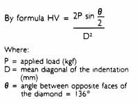
Knoop Scale
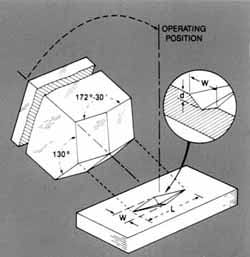
ASTM E384 (Vol. 03.01) Standard Test Method for Microhardness of Materials describes the Knoop hardness test as “… the number obtained by dividing the applied load in kilograms—force by the projected area of the indentation in square millimeters, computed from the measurement of the long diagonal of the indentation … [formed by] a highly polished, pointed, rhombic based, pyramidal diamond with included longitudinal edge angles of 172º 30 min (± 5 min) and 130º 0 min … the four faces of the indenter shall be equally inclined to the axis of the indenter (within ± 30 min) and shall meet at a sharp point. The line of the junction between opposite faces (offset) shall not be more than 1.0 µm …”
The Knoop hardness number, reported as HK, is the ratio of the force applied to the indenter, P (kgf) to the unrecovered projected area, A (mm2), of the indentation.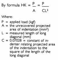
Knoop v. Vickers
In the most general of terms, for a given load and material, a Vickers indenter may penetrate approximately twice as much and the diagonal dimension may be approximately 1/3 of that achieved by a Knoop indenter. The conclusion drawn is that the Vickers test is less sensitive to certain “surface conditions” than the Knoop test.
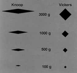
While this is true in the most general of terms, each test has specific advantages dependent on the material, “surface condition” and the specimen configuration, i.e., a Vickers test allows for a wider range of applied forces as well as corrections for spherical, cylindrical, convex and concave surfaces. The microhardness of a specimen, when the desired results are not well defined or predetermined, are most often arrived at empirically.
Shown at the left is a relative comparison of indents formed with various loads on a given material.
Credits:
Information Author & Images (edited and modified for presentation):
Wilson—Shore Instruments, Division of Instron Corporation, Canton, MA
Contact CCSi to request calibration services.