CCSi DuroMatters: Basic Durometer Testing Information
CCSi offers this description of the principles of ASTM D2240 durometer hardness testing to provide a basic understanding of the concepts.
The information is general in nature, is pertinent only to ASTM D2240, ASTM F1957, ISO 7619, ISO 868, and other similar methods of ‘Shore Scale’ durometer hardness determination and not designed as a definitive guide. CCSi freely answers questions regarding specific hardness testing questions, simply eMail CCSi.
CCSi DuroMatters: Durometer Instrument Background
- The material is generally termed “rubber or rubber—like”. Specifically, ASTM D2240 durometer hardness testing is restricted to thermoplastic elastomers, vulcanized (thermoset) rubber, elastomeric materials, cellular materials, and some plastics as defined by the ASTM Committee on Terminology in ASTM D1566.
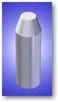
- The indentor has a specific geometry and resistance to movement. The resistance to movement of the indentor is accomplished through a calibrated spring.
- The conditions are specifically defined in ASTM D2240. In general terms, it outlines the preparation and configuration of the test specimen as well as the details of performing the durometer hardness test.
Note: ASTM D2240 may be found in Volume 09.01 of the American Society for Testing and Materials“Annual Book of ASTM Standards.” CCSi highly recommends obtaining the most recent edition of the method as it has changed dramatically in the past 2 years! - The movement of the indentor is related to the durometer hardness of the material, e.g. the more the indentor moves the higher the indicated durometer value of the material.
- The penetration of the indentor into the test specimen is inversely proportional to the durometer hardness value of the test specimen, e.g., the more indentor penetration into the test specimen, the lower the durometer hardness value.
CCSi DuroMatters: Durometer Instrument Function
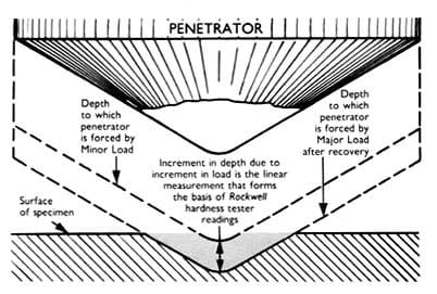
Many hardness testing methods employ a technique that “permanently” deforms the material being tested, the depth of the indentation or other characteristics of this “static deformation” are then measured to determine a hardness value.
In durometer hardness testing, the material does not remain “permanently” deformed when an indentation is made, i.e., the material is generally highly elastic and the penetration depth of the indentor is not static, nor is the indentation in the material permanent.
To overcome these material specific characteristics, a durometer measures the relative movement of the the indentor, rather than the depth of the indentor penetration, or other characteristic of a “static deformation” of the material.
Due to the potential energy (pre—load) of the calibrated spring, the elastic characteristics of the material and other factors, the determination of indentor movement may not necessarily begin at the moment of indentor to specimen surface contact and it may also change over time, thus requiring a determination of indentor movement that is also time specific.
This movement is translated, either electrically, mechanically, or electro—mechanically to an analog or digital scale indicating the relative durometer hardness value.
The determination of the final durometer hardness value is achieved by visually reading the analog indicating hand within 1s of the “moment of cessation” of the numerical increase of the indication, which is the generally agreed upon time specific reference.
In analog type durometers, the indication of the “moment of cessation” may also be determined by way of an integral 2nd hand, a ‘maximum’ or ‘lazy’ hand, which follows the indicating hand and retains the maximum value achieved.
The introduction of a ‘maximum’ or ‘lazy’ indicator imposes a nominal drag coefficient on the mechanism and is not thought to adversely affect achieved values, except in those durometer types having a spring force of 113 gf or less.
Durometers that are of the digital electronic variety, the moment of maximum indentor penetration, i.e. the “moment of cessation”, may be determined electronically. These may also be equipped with adjustable timing mechanisms which may be used to compensate for comparing the determinations to those attained using a non—electronic durometer.
CCSi DuroMatters: Important Durometer Components
- A Presser Foot, normally the bottom most surface of the instrument housing, machined to be flat and perpendicular to the indentor and containing an orifice through which the indentor protrudes.
An Indentor of varying designs, dependent upon the relative hardness and configuration of the material being tested. The indentor protrudes through the presser foot at a specified distance. The change in this distance, as it is applied to the test specimen, is translated into a durometer hardness value. - A Calibrated Spring which is, most often, mechanically attached to the indentor. The calibrated spring provides specific resistance to the movement of the indentor. The force required to cause indentor movement is proportional to the hardness value of the test specimen (inversely proportional to the indentation into the test specimen).
It is worthy to note that recent technological advancements in electronics, specifically miniaturization and micronization, has allowed the introduction of load cell, pressure/force transducer, style technologies. - These are far more linear, accurate and precise than the springs presently in use and will advance the science of durometer hardness testing in the very near future!
- An Indicator which displays the hardness value achieved. This indicator may be a digital display, usually via a LVDT (linear voltage differential transformer) which measures the movement of the indentor. It may also be an analog display, mechanically attached to the indentor assembly, making use of an indicating hand against a graduated dial.
CCSi DuroMatters: Durometer Types and Specifications
The combination of specific spring forces and indentor configurations, in the most general of terms, provides the various durometer hardness scales, i.e., A, B, C, D, DO, etc. These scales are properly referred to as durometer types, i.e., a durometer type is specifically designed to determine a specific scale, and the scale does not exist separately from the durometer.
Currently in ASTM D2240—04, Types A, B, C, D, DO, E, O, OO, OOO and OOO—S, M, and R are recognized. A summary of the changes from previous editions of D2240 are:
- Types A, B, C, D, DO, O and OO remain unchanged;
- Type E was included to reflect changes in ISO 7619. This durometer type is very similar in configuration to the durometer type commonly known as “Asker C”;
- Types OOO and OOO—S were changed to differentiate the differences between the OOO types manufactured by Shore® (now designated as OOO—S) and other manufacturers (designated as OOO) as well as defining the indentor configurations;
- Type M, or microhardness type, was incorporated in D2240 in 2000, and has remained unchanged;
- Type R is a designation, rather than a true ‘type’. The R designation specifies a presser foot diameter (hence the R, for radius, obviously D could not be used) of 18 ± 0.5 mm (0.71 ± 0.02 in) in diameter, while the spring forces and indentor configurations remain unchanged;
- The R designation is applicable to any D2240 Type, with the exception of Type M;
- The R designation is expressed as Type xR, where x is the D2240 type, e.g., aR; dR; etc.
- The R designation also mandates the employment of an operating stand.
The twelve durometer types enumerated in ASTM D2240—03 are made up of combinations of five different spring forces and seven indentor configurations:
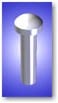
Type A Indentor:
- Configuration: 35º Truncated (Frustrum) Cone
- Diameter: 1.40 Ø mm (0.050 inch)
- Extension: 2.54 mm (0.100 inch)
- Employed by D2240, Types A and C
- Employed by ISO 868 & 7619, Type A
Spring Force:
- Type A — 822 gf (8.05 N)
- Type C — 4536 gf (44.45 N)
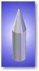
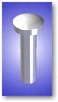
Type D Indentor:
- Configuration: 30º Cone
- Diameter: 1.40 Ø mm (0.050 inch)
- Extension: 2.54 mm (0.100 inch)
- Employed by D2240 Types B and D
- Employed by ISO 868 & 7619, Type D
Spring Force:
- Type B — 822 gf (8.05 N)
- Type D — 4536 gf (44.45 N)
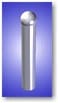
Type E Indentor:
- Configuration: 2.5 mm (0.100 in) Spherical Radius
- Diameter: 4.5 Ø mm (0.200 inch)
- Extension: 2.54 mm (0.100 inch)
- Employed by D2240 Type E
- Employed by ISO 7619 Type E
Please note that the ISO 7619 Type E specifies the D2240 R designation. Therefore, a D2240 Type E conforming to ISO 7619 would necessarily be a D2240 Type eR.
Spring Force:
- Type E — 822 gf (8.05 N)
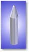
Type M Indentor:
- Configuration: 30º Cone
- Diameter: 0.79 Ø mm (0.031 inch)
- Extension: 1.25 mm (0.050 inch)
- Employed by D2240 Type M
- Employed by ISO 7619, Type M
Please note that ASTM D2240 and ISO 7619 Type M specify the employment of an operating stand.
Spring Force:
- Type M — 78 gf (0.0044 N)
Type E Indentor:
- Configuration: 2.5 mm (0.100 in) Spherical Radius
- Diameter: 4.5 Ø mm (0.200 inch)
- Extension: 2.54 mm (0.100 inch)
- Employed by D2240 Type E
- Employed by ISO 7619 Type E
Please note that the ISO 7619 Type E specifies the D2240 R designation. Therefore, a D2240 Type E conforming to ISO 7619 would necessarily be a D2240 Type eR.
Spring Force:
- Type E — 822 gf (8.05 N)
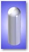
Type OOO Indentor:
- Configuration: 0.635 mm (0.250 inch) Spherical Radius
- Diameter: 10.7/11.6 Ø mm (0.420/0.455 inch)
- Extension: 2.54 mm (0.100 inch)
- Employed by D2240 Type OOO
Please note that ASTM D2240 distinguishes a heretofore unrealized difference between the Type OOO and OOO-S that were both commercially known as Type OOO.
Spring Force:
- Type OOO — 113 gf (1.111 N)
Type OOO-S Indentor:
- Configuration: 10.7 mm (0.420 inch) Radius
- Diameter: 12.0 Ø mm (0.470 inch)
- Extension: 5.0 mm (0.200 inch)
- Employed by D2240 Type OOO-S
Please note that the Type OOO-S was previously marketed by Shore® as a Type OOO.
Spring Force:
- Type OOO-S — 197 gf (1.932 N)
CCSi DuroMatters: Durometer Testing Mythology
The issue that moves durometer testing from the realm of simplicity to the world of complexity, is not the instrumentation but the material being tested!
Durometer hardness is dependent on the elastic modulus and viscoelastic behavior of the material being tested. Inferences are often drawn between durometer hardness and other physical characteristics of the material being tested. Studies of “hysteresis” and “Young’s Modulus” are possible with durometer hardness testing instruments, however this is beyond the scope of this discussion.
There are, in many instances, direct non—linear relationships between durometer hardness and other physical characteristics, however it is paramount that these be treated as material specific, with the understanding that empirically derived correlations are to be considered strictly individual relationships!
“The geometry of the indentor and the applied force influence the measurements such that no relationship exists between the measurements obtained with one type of durometer and those obtained with another type of durometer.” (ASTM D2240).
Durometer hardness, in other words, is not only material specific, but the values attained with one durometer type should never be correlated to those attained with another durometer type!
Credits
Author:
- Michael Kent Warner, Cape Coral, Florida USA
Images (modified for presentation):
- Kobunshi Keiki Co., Ltd., Tokyo, Japan
- Wilson-Shore Instruments, Division of Instron Corporation, Canton, MA
- Corporate Consulting, Service, & Instruments, Inc., Akron, OH
Contact CCSi to request calibration services.